
WIKA 732.15.160 CryoGauge
緊湊型全鋼低溫冷凍用不銹鋼差壓表
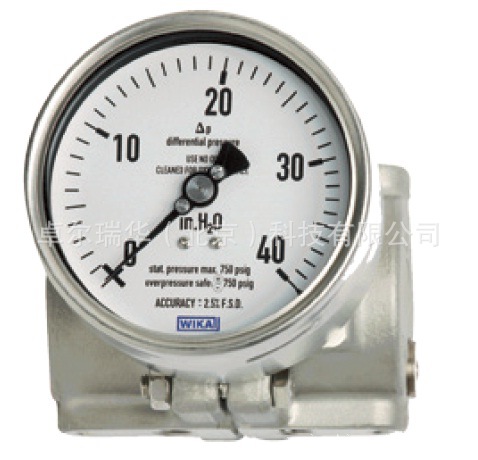
Differential pressure gauge
Model 712.15.100, Cu-alloy
Model 732.15.100, stainless steel version
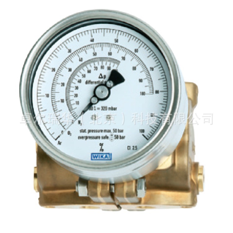
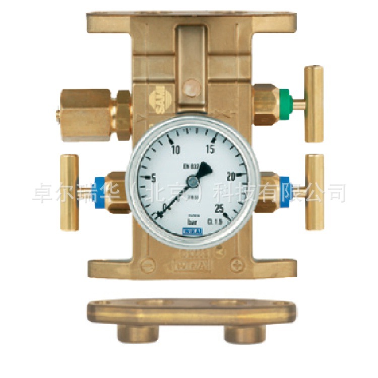
Fig. top: Differential pressure gauge model 712.15.100
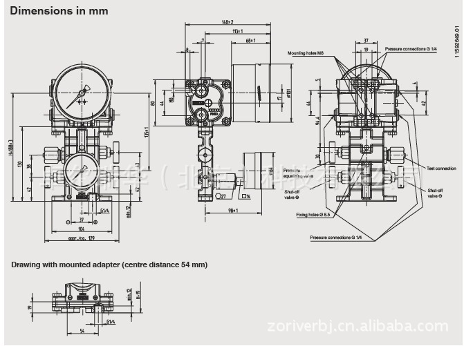
Fig. centre: Option valve manifold with working pressure indication
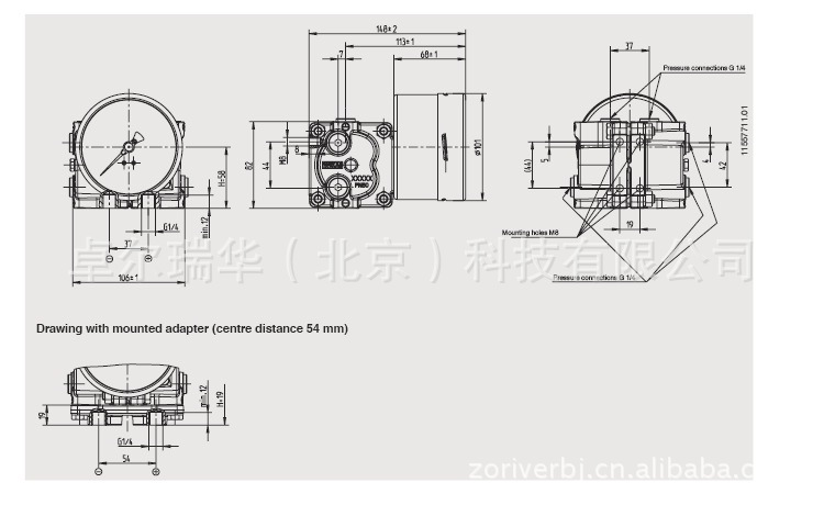
Fig. bottom: Option adapter for flange mounting
Applications
■ Level measurements in closed tanks, particularly in cryotechnology
■ Filter monitoring
■ Monitoring and control of pumps
■ For gaseous and liquid media that are not highly viscous or crystallising and have no suspended solids
Special features
■ Differential pressure measuring ranges from 0 … 80 mbar to 0 ... 1725 mbar
■ High working pressure (static pressure) of 50 bar
■ Overpressure safety either side up to 50 bar
■ Very compact design
■ Optionally compact valve manifold with working pressure indication
Debion
These high-quality gauges are characterised by their compact and robust design and are primarily used for level measurement on liquid gas tanks.
An optional valve manifold for flange mounting with working pressure indication makes the central measurement of both level and working pressure possible in the one instrument.
The level display can be supplied with an optional, integrated 4 … 20 mA, 2-wire transmitter. Switch contacts for level and working pressure, as well as a transmitter for the working pressure can be retrofitted on site.
The standard centre distance of 37 mm between the process connections can be adapted to a custom centre distance of 31 mm or 54 mm using adapters for flange mounting.
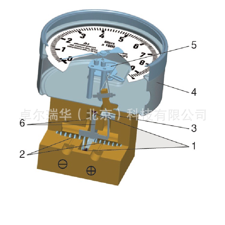
Design and operating principle
Pressures p1 and p2 act on the media chambers ⊕ and ?, which are separated by an elastic diaphragm (1).
The differential pressure (Δp = p1 - p2) leads to an axial deflection of the diaphragm against the measuring range spring (2).
The deflection, which is proportional to the differential pressure, is transmitted to the movement (5) in the indicating case (4) via a pressure-tight and low friction lever mechanism (3).
Overpressure safety is provided by bl bolsters (6) resting against the elastic diaphragm.
Illustration of the principle
Mounting according to affixed symbols,
⊕ high pressure and ? low pressure
Standard version
Differential pressure gauge
Model 712.15.100
Model 732.15.100
Specifications
Nominal size NS 100 (level indication)
Accuracy class 2.5 (option: Class 1.6 or class 1.0)
Scale ranges 0 ... 80 mbar to 0 ... 1725 mbar
Max. working pressure (static pressure) 50 bar
Overpressure safety either side up to 50 bar
Permissible ambient temperatures -40 °C … +80 °C, -40 °C … +60 °C with oxygen
Permissible medium temperatures -40 °C … +80 °C, -40 °C … +60 °C with oxygen
Ingress protection IP 65 per EN 60529 / IEC 529
Process connections (wetted)
Standard 2 x G 1/4, female, lower mount (LM), centre distance 37 mm
Option with adapter see page 5
Measuring cell flanges (wetted) Model 712.15: Cu-alloy CW614N (CuZn39Pb3)
Model 732.15: Stainless steel 316L
Pressure elements (wetted) Compression spring, stainless steel 1.4310
Separating diaphragm, NBR
Transmission parts, stainless steel 1.4301 and 1.4305
Movement Wear parts stainless steel
Dial White aluminium (see section 'Scale designs')
Pointer Adjustable pointer, black aluminium
Zero adjustment By means of adjustable pointer
Case / slip-on bezel Stainless steel, with clip fasteners
Window Polycarbonate (PC)
Scale designs
The dials can be made to customer‘s requirements and also with multiple scales.
These can be printed with all usual units on them, e.g. kg, litre, m3, mmH2O, inchH2O, % etc.. Red marks for maximum fill level, customer logos and other custom printing are likewise possible. If desired, we can carry out the calculation
for the tank fuel level from drawings of the tank geometry, and then make the appropriate scales.
Dimensions in mm
Option
Valve manifold (wetted) with mounted working pressure gauge
Specifications
Valves 2 x shut-off valve, 1 x pressure equalising valve
Test connection M20 x 1.5 with sealing cap (DIN 16287-A)
Valve body Model 712.15: Cu-alloy CW614N (CuZn39Pb3); model 732.15: Stainless steel 316L
Spindle with conical nipple Model 712.15: Cu-alloy; model 732.15: Stainless steel 316L
Packing/sealing NBR/PTFE
With the valve fully-opened, the spindle area is isolated from the process by a bllic seal, the packing is not loaded and the spindle thread is not in contact with the measured media.
Working pressure gauge
Standard Model 232.50.63, wetted parts stainless steel
(for specifications and design details see data sheet PM 02.02)
Option Model 212.20.100, wetted parts Cu-alloy
(for specifications and design details see data sheet PM 02.01)
With a single order, all parts necessary for the fitting to the differential pressure gauge are included in the delivery: 4 x hexagon screws M8 x 16 , 2 x O-ring seal
Option
Adapter for process connection
The adapters can be flange mounted either directly to the differential pressure gauge or to the valve manifold.
Specifications
Material Model 712.15: Cu-alloy CW614N (CuZn39Pb3); model 732.15: Stainless steel 316L
Process connections (wetted) 2 x G 1/4, female, lower mount (LM), centre distance 31 mm or 54 mm or 2 x 1/4 NPT, female, centre distance 31 mm, 37 mm or 54 mm
Option
Transmitter for level indication
Standard version model 891.44
Ex version model 892.44
WIKA differential pressure gauges with an integrated model 89x.44 transmitter combine all the advantages of an on-site mechanical display with the demands modern industry makes for electrical signal transmission for the acquisition of
measured values.
The transmitter is integrated into the case of the level display. With multiple scales (option) the output signal of 4 ... 20 mA corresponding to each, can be stored in a microprocessor.
The output signal can be changed over to the desired fluid type by rotating the optional BCD switch (accessible through a cover cap on the left side of the case) using a screwdriver.
Transmitter for level display
With a single order, all parts necessary for the fitting to the differential pressure gauge or to the valve manifold are included in the delivery: 2 x hexagon screws M8 x 16, 2 x hexagon screws M8 x 28, 2 x nut M8 and 2 x O-ring seal
Specifications
Models 891.44 and 892.44 (Ex version)
Supply voltage UB DC V 12 < UB ≤ 30 (min. 14 with Ex version)
Influence of supply voltage % Full scale/10 V ≤ 0.1
Permissible residual ripple % ss ≤ 10
Output signal 4 … 20 mA, 2-wire
Permissible max. load RA for non-Ex versions, model 891.44:
RA ≤ (UB - 12 V) / 0.02 A with RA in Ohm and UB in Volt for Ex versions, model 892.44:
RA ≤ (UB - 14 V) / 0.02 A with RA in Ohm and UB in Volt
Effect of load % Full scale ≤ 0.1
Adjustment
Zero point, electrical Adjustment of the zero point through brief bridging of terminals 5 and 6 or using the 'scale selection switch' option, selectable via button 1)
Scale selection 4 scales selectable via BCD switch
Linearity % of span ≤ 1.0 % (terminal b)
Permissible
ambient temperatures °C -40 … +80, -40 … +60 with oxygen
Compensated temp. range °C -40 … +80
Temperature coefficients in the compensated temp. range
Mean TK of zero % of span / 10 K ≤ 0.3
Mean TC span % of span / 10 K ≤ 0.3
1) Only possible within 30 seconds of connecting the supply voltage
?CE conbity
EMC directive ATEX directive
2004/108/EC, EN 61326 emission (group 1, class B) and interference immunity (industrial application) 94/9/EC, II 2 G Ex ia IIC
Further specifications Models 891.44 and 892.44 (Ex version)
Conbity specifications Ex version
■ Supply voltage Ui DC V 14 ... max. 30
■ Short circuit current Ii mA max. 100
■ Power Pi W max. 1
■ Internal capacitance Ci nF 12
■ Internal inductance Li mH negligible
Medium temperature °C -40 … +80, -40 … +60 with oxygen
Ambient temperature °C -40 … +60 (T6)
Electrical connection Angular connector, 180° rotatable, wire protection, cable gland M20 x 1.5, incl.strain relief, connection cable: Outer diameter 7 ... 13 mm, conductor cross-section 0.14 ... 1.5 mm2, temperature resistance up to 60 °C
Wiring protection Protection against reverse polarity and overvoltage
Ingress protection IP 65 per EN 60529 / IEC 529
Wiring details, 2-wire
Earth, connected to case 1)
UB+/Sig
+0 V/Sig-
Terminals 3, 4, 5 and 6: only for internal use 1) This connection must not be used for equipotential bonding. The instrument must be incorporated in the equipotential bonding via the process connection.
?Option
Transmitter for working pressure indication
Standard version model A-10
or Ex version model IS-20
The transmitters for the working pressure are screwed in sideways on the left side of the minus media chamber and can, if necessary, be retrofitted on site.
Pressure connection of the transmitter:
G 1/4 (male)
Option
Switch contacts for level and/or working pressure indicators A modular system of electromechanical and electronic switch contacts with plug connection, also suitable for retrofitting on site, can be fitted both to the level display and to the working
pressure indication. They consist of self-contained units, which can be fitted to any pointer pressure gauge within a few minutes. The connection to the instrument pointer is made by means of a special yoke so that a carrier pin at the pointer itself is not needed. The set value pointer of the installed switch contacts are adjusted, from the outside, to the value at which the switching operation is to take place, using the adjustment lock with a separate or integral key. A coupler connector, an M3 x 20 centring screw and a seal are included in the delivery.
Selectable are the following single and double contact models built into a self-contained unit
■ Model 828 1) , magnetic snap-b contact
■ Model 838 1) , inductive contact gauge
Switching functions
The following applies, as a general rule, to the contact functions of the model 828 1) in connection with our standard settings:
Index 1 according to the contact type no. means:
Contact closes the circuit when the set point is exceeded
Index 2 according to the contact type no. means:
Contact opens the circuit when the set point is exceeded
Index 3 according to the contact type no. means:
When the set value is exceeded, one circuit is opened and one circuit is closed simultaneously (change-over contact)
The following applies, as a general rule, to the contact functions of the model 838 1) inductive contacts in connection with our standard settings:
Index 1 according to the contact type no. means:
Contact closes the control circuit when the set point is exceeded (flag disengages from control head)
Index 2 according to the contact type no. means:
Contact opens the control circuit when the set point is exceeded (flag engages with control head)
The switching functions are based on a clockwise rotational
motion of the instrument pointer.
歡迎致電咨詢訂購WIKA 712.15.100 732.15.160 低溫行業(yè)用銅差壓壓力表 無粘稠液體
電話:010-51669912 56291930 15910733293
傳真:010-51669912
QQ:823377546 1491421115 2636968574
公司官網(wǎng):http://www.zoriver.cn http://www.zoriver.com.cn
